



Installing your Slimline 5000 or Platinum 7000 Cavity System
What's in the Box?
Cavity Unit Components
- 1 × Cavity Pocket
- 1 × Head Track Assembly
- 1 × Closing Jamb**
- 2 × Removable Fillets*
- 1 × Cavity Hardware Kit
- 1 × Glide Guide Kit (QLD, NSW, WA Only)
- 1 × Reversible Door Guide (VIC, SA Only)
Glide Guide Kit (OLD, NSW, WA Only)
- 2 × Glide Guide Strips
- 2 × Nylon Finger Guides
- 2 × 15mm Round Head Screws
- 10 × Panel Pins
*NSW & SA only for Platinum 7000
*QLD, VIC & WA only for Slimline 5000 & Platinum 7000
**Not applicable to Slimline Cavities in NSW
Cavity Hardware Kit
- 1 × Soft Closer Sliding Door Roller
- 1 × Sliding Door Roller
- 2 × Trigger Blocks
- 2 × QuickFix Door Brackets
- 2 × M8 50mm Hex Head Roller Bolts
- 8 × Hex 8G 30mm Self-Tapping Screws
- 1 × Spanner
- 4 × Foldable Snap Caps
- 1 × 25mm Concrete Nail
- 8 × 8G 38mm Countersunk Phillip Screws
- 8 × 6G 13mm Countersunk Phillip Screws
- 2 × 8G 19mm Pan Head Screws
- 1 × 14G 50mm Hex C4 Type 17 Screw
- 2 × 8G 25mm Phillip Button Head Screws
- 1 × 60mm Bumper Stop
- 2 × 10mm Bumper Stops
- 8 × 8G 19mm Phillip Button Head Self-Drilling Metal Screws
- 3 × 12G 65mm Hex Self-Drilling Metal Screws
Installation
Important Information
Using the Cavity Hardware Kit provided and following these step-by-step instructions, you can achieve a smooth operating, professional installation with confidence.
Refer to the following for detailed guidance on each step. We recommend using the door from the beginning of the installation process to ensure all components are aligned and installed correctly.
Single cavity units have a door weight limit of 80kg. Double cavity units have a door weight limit of 80kg per door. Cavity units are not load bearing. When installing double cavity units, the track must be fixed to a structural member. Screw through the centre of the track. Only use button head screws (not provided in fittings).
For Platinum 7000 Cavity Units:
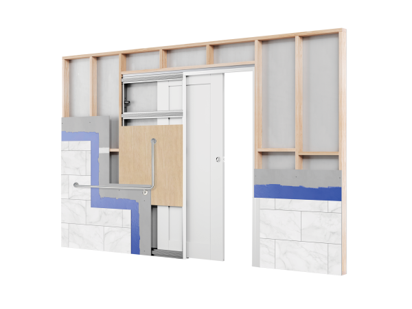
Take care when installing the cavity unit into wall-tiled areas. Please consult with the substrate/tile manufacturer for their recommended fixing and tiling methods in accordance with the relevant standards.
Please note, only Platinum Cavity Systems are suitable for tiled walls.
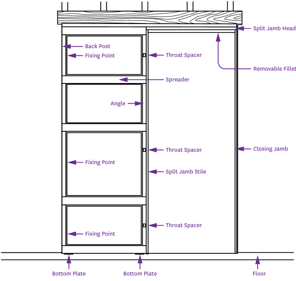
Do not remove the temporary throat spacers in the opening of the cavity throat until wall sheeting is complete. Failure to comply will void warranty.

Flush Jamb & Flush Pull
For a Flush Jamb fitment, install the 2 x 10mm Bumper Stops onto the edge of the door, closest to the Cavity Pocket. To convert a Flush Jamb cavity into a Flush Pull unit, install 1 x 60mm Bumper Stop onto the edge of the door, closest to the Cavity Pocket and central to the height of the door.
Ensure the position of the bumpers are not in line with the back post fixing screws. Some unit sizes/types may not be available in all states. Cavity unit depicted with door in the fully open position.

Soft Closer Primed Position
The soft closer has 2 positions, the neutral (not primed) position and the correct (primed) position which is achieved by simply sliding it into position.

1. Fit the Head Track Assembly
Fit and screw the Head Track Assembly to the Cavity Pocket using the appropriate screws for your type of Cavity unit.
- Steel Cavity units: 8 × 8G 19mm Phillip Button Head Self-Drilling Metal Screws.
- Timber Cavity units: 8 × 6G 13mm Phillip Countersunk Screws.
Do not remove the temporary throat spacers until wall sheeting is complete. Failure to comply will void warranty.

2. Fix the Closing Jamb
Using a 50mm screw or nail (not provided in fittings), secure the Split Jamb Head to the Closing Jamb on both sides.
- Pre-drilling is required on both sides before fastening.

3a. Check the Cavity Unit and Opening
Complete the following checks:
- Squareness of the Cavity Unit
- Squareness of the Opening
- Floor level and clearance required for the chosen floor coverings
Pack as required to achieve a square and level installation.
3b. Install the Cavity Unit
Place the Cavity Unit into the wall opening, ensuring it is plumb.
- Fix the back post to the brick or stud work. For Platinum Cavity Units we recommend using 3 × 12G 65mm Hex Self-Drilling Metal Screws.
- Fasten the base of the unit to the floor through the base plate using the appropriate fixings for your substrate. For concrete we recommend 1 × 25mm Concrete Nail for Steel Cavity units.
- Fix the back post to the brick or stud work using nails for Timber Cavity unts.
Do not remove the temporary throat spacers until wall sheeting is complete through base plate.

4a. Fit the Rollers
Fit the Rollers in the order and orientation shown.
Ensure 2 × M8 50mm Roller Bolts are installed into the Rollers before hanging.

4b. Install the Soft Closer Trigger Block
Insert the soft closer Trigger Block inside the Cavity Unit at the distance specified below.

5. Attach QuickFix Door Brackets
Attach the QuickFix Door Brackets to the top of the door using 8 × 8G 30mm Hex Self-Tapping Screws.
- Position one bracket 100mm in from the front edge of the door and the other 70mm in from the back edge of the door.
- Ensure QuickFix Door brackets centred to the thickness of the door.

6. Install Glide Guide Strips (QLD - NSW - WA only)
Using the Glide Guide Kit, trim the Strips to match the width of the door.
- Use 10 Panel Pins on the bottom edge of the door, 5 pins on each side (front and back) of the door, to secure each Strip in place as shown.

7. Hang the Door
Adjust the Rollers so they are accessible from the door opening. Once positioned, hang the door onto the QuickFix Door Brackets and use the Spanner provided to adjust the door height as required.
Ensure the door is level and plumb, using a spirit level.


8. Install the Reversible Door Guide (VIC - SA only)
Slide the Reversible Door Guide along the groove into the bottom of the door.
Loosely screw the guide to the Split Jamb using 2 × 8G 25mm Phillip Button Head Screws.
- Centre the door in the Cavity Pocket.
- Fully tighten the screws into the Reversible Door Guide.


9. Attach Removable Fillets
Attach the Removable Fillets using 4 × 8G 35mm Phillip Countersunk Screws and 4 × Foldable Snap Caps, by screwing through the Snap Caps into the Removable and Fixed Fillets.
Refer to the diagram for your state, using the arrows on the image.

10. Fix Nylon Finger Guides (QLD - NSW - WA only)
Fix the 2 × Nylon Finger Guides from the Glide Guide Kit to the Split Jamb.
- Position the flexible portion in the throat of the cavity.
Finishing
Ensure fixing screws from the plasterboard do not penetrate through the pocket spreaders. Ensure the head of the unit is not load bearing.
If installing a double Cavity Unit, install the double door stop into the headtrack and adjust position until doors meet in the middle.
Double Cavity Units
Using the Head Track Joiner (NSW Only)


1. Trim off the Head Track
Trim 18mm off the head track as shown. Trimming must be from the end with the roller entry cutout.
2. Fit and screw the Head Track Assembly
Fit and screw the Head Track assembly to the Cavity Pocket
Use the appropriate screws for your type of Cavity unit.
- Steel Cavity units: 8 × 8G 19mm Phillip Button Head Self-Drilling Metal Screw
- Timber Cavity units: 8 × 6G 13mm Phillip Countersunk Screws.
Do not remove the temporary throat spacers in the opening of the cavity throat until the wall sheeting has been completed. Failure to comply will void warranty.


3. Join the tracks and secure
Join the two tracks together by user the supplier track joiner. This slides onto the tracks to secure them together.

4a. Install the Double Door Stop into the track
Install the Double Door Stop into the Track as shown.


4b. Install the Double Door Stop into the track
Once in the track, adjust the position of the stops until the doors meet in the middle.